Modern Cleanroom Computation
When CFD Secures the Manufacturing Process of Vaccines
-
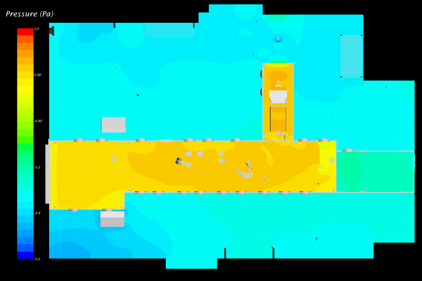 Creaform: Pressure distribution in horizontal plane – before (left) and after (right) design adjustments
 -
 Creaform: Streamlines in close contact with the table and evacuating through the vials shoulders
 -
 Creaform: Impinging flow on accumulation table
 -
 Creaform: Velocity vectors in section plane at capping arm elbow – original design, modified design with aerodynamic deflectors
 -
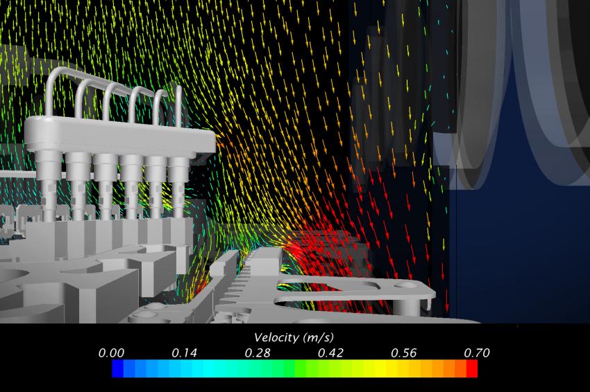 Creaform: Velocity vectors in section plane at capping arm elbow – original design, modified design with aerodynamic deflectors
 -
 Creaform: Pressure distribution in horizontal plane – before (left) and after (right) design adjustments
 -
 Creaform: Principal boundary conditions
 -
 Creaform: Hexahedral mesh of vials conveyor
 -
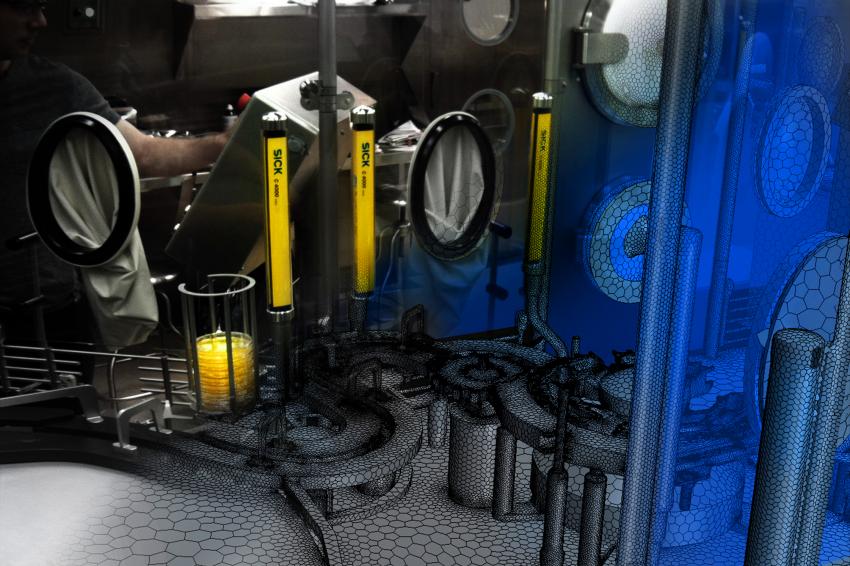
 Creaform: Room scan using a mid-range scanner
 -
 Creaform: Vaccine filling cleanroom
ReinRaumTechnik 3/2015 Englische Ausgabe:
Bringing vaccine manufacturing vali-dation to the next level using CFD: Creaform upgrades the regulatory compliance process of pharmaceutical environments.
Creaform was asked to assist in the design of a cleanroom, by performing a complete 3D reconstruction of the geometry of the room, and using this to carry out detailed CFD simulations. The cleanroom in question is used in the manufacture of influenza vaccine, and the aim of the study was to design an efficient aerodynamic barrier that would mitigate the risk of contamination. The demonstration was convincing and CFD simulations shed light on phenomena that traditional smoke tests, still used for regulatory compliance of pharmaceutical environments, had never been able to resolve before.
The pharmaceutical cleanroom in this study is a critical environment requiring a high level of protection against contamination. While the cleanroom itself is a grade B environment, the interior of the RABS (Restricted Access Barriers) is protected with screened barriers and HEPA (High-Efficiency Particulate Air) clean-air filtration, such that it is rated as a grade A critical zone. The vaccine filling machine had to be incorporated in the RABS, leading to many specific flow interactions which could not be predicted prior to installation, neither by the manufacturer nor the integrator. It was therefore necessary to thoroughly understand the fluid flow behavior in order to ensure proper flow path around non-sterile components of the machine. Not only was the regulatory compliance of the cleanroom at stake, but with the amazing production rate of the line (hundreds of vial fillings per minute), a contamination would represent a considerable financial loss because it leads to the waste of vaccine doses.
In that context, Creaform’s 3D modeling and CFD (Computational Fluid Dynamics) solutions came in very handy. Using basic STL files such as the ones created by 3D scanners, the engineering team numerically reproduced the cleanroom in CAD (Computer-Aided Design) software and performed a series of CFD simulations using STAR-CCM+.
The Stakeholders
Creaform’s mission is to develop, manufacture and market cutting edge portable 3D measurement and analysis technologies that increase productivity. Through its expertise and the passion and commitment of its employees, Creaform helps companies from the manufacturing industry to seamlessly create, simulate, verify, and collaborate in 3D, significantly enhancing their turnaround times and profitability. Through its 3D Engineering Services department, they develop CFD simulation techniques in multiple fields like transport, energy, environment, civil works, electronics and HVAC. Creaform was responsible for the CAD reproduction of the entire pharmaceutical production line and surrounding cleanroom, the CFD simulation of the air flow with RABS and HVAC systems in operation, and the assessment of aerodynamic deflectors to optimize flow behavior around non-sterile components.
Laporte is a consulting firm specialized in bio-pharmaceutical, food & beverage and industrial engineering. Its employees have experience in a wide array of services in the process, building and infrastructure, automation, packaging and regulatory compliance fields. Laporte was in charge of the process design, installation and commissioning for the pharmaceutical facility upgrade. These tasks include the HVAC design and the integration of the filling machine in the RABS system. Laporte was also responsible for the smoke tests used for regulatory compliance.
Computational Geometry
A typical headache when carrying out a CFD analysis is not having the geometry available. An even bigger headache is not having confidence in the numerical geometry because the as-built drawings are incomplete or the geometry has changed over time. This situation brings the engineers to constantly question the CFD results. Creaform, by supplying efficient 3D scanning solutions, ensures high quality numerical reproduction. Creaform also manufactures fast, portable and easy to use scanners that provide metrology-grade accuracy and resolution. For CFD applications in the HVAC industry, it is quite common for Creaform’s engineers to combine the scan of an entire room acquired by a mid-range scanner with the precise scan of specific parts using one of Creaform’s handheld scanners. The result is a clean STL file such as the one built for the pharmaceutical cleanroom.
The numerical geometry of the cleanroom includes the walls and furniture, the HEPA filtration, the HVAC system, the physical barrier with gloved access (windows surrounding the production line), the control panels as well as the RABS itself with the accumulation table for vials, the conveyor, the filling needles, the capping machine and many measurement instruments, all of which were accounted for in the CFD simulations thanks to the wrapping capabilities of STAR-CCM+.
Simulations
Precise and representative boundary conditions are critical for the cleanroom simulation. They were carefully determined using very recent data acquisition:
- Laminar flow equipment performance evaluation providing air velocity profiles for each diffuser of the HEPA filtration system;
- Ventilation balancing measurements for the HVAC system including return ducts;
- Precise pressure gaging in adjacent rooms for secondary air flow rates through wall openings for conveyor and through the door contour.
Turbulence modeling was achieved with the RANS approach and more specifically with the SST (Menter) k-ω model, thus limiting the results to steady state. The All y+ Wall Treatment was used because many near wall cells fell within the buffer region of the boundary layer. The control over the entire surfaces to force viscous sublayer resolution was computationally expensive and judged unnecessary. Indeed, calculation of viscous forces is not required and flow separation occurs at cutting edges, so its prediction is trivial. Consequently, the mesh is polyhedral and does not make use of prism layers. The prioritized cell refinement was the one allowing to capture the surface details of the machine components, resulting in a cell count of 5.6 million for initial runs (setup check and initial solution) and of 18.4 million for final runs. Simulations made use of the coupled flow model with a 2nd order discretization.
Overall Pressure Distribution
Ideal flow conditions just above the conveyor level consist of a perfectly vertical flow. Pressure distribution in the horizontal plane is thus very important and must be as uniform as possible inside the RABS. The first CFD simulation of the cleanroom showed a small pressure gradient that was sufficient to induce a longitudinal component to the velocity vectors inside the RABS. Laporte engineers designed deflectors to redistribute the pressure in the capping section and removed the partition that provoked a pressure increase in the vials accumulation section. Combined with the modular adjustment of the HEPA filtration, these modifications significantly improved the pressure distribution in the RABS. The CFD simulation correlates well with the smoke tests performed with the new design and confirmed the improvement efficiency.
Transverse Flow
With the longitudinal flow corrected, Laporte and Creaform focused on transverse velocity components in the vicinity of non-sterile machine components. The CFD simulations highlighted two similar undesired situations: one around the needles holder and one around the capping arm. Both components are non-sterile and the air draft from underneath the physical barrier induces a significant transverse velocity component. As can be seen in Figure 6, this phenomenon drives particles in contact with the arm directly toward the vials that are conveyed at the level of the toothed plate. The aerodynamic deflector visible on Figure 6 was tested in simulation and provoked the shift of the air draft towards the machine floor. It caused the streamlines in the vicinity of the arm to reach the underside of the conveyor, keeping the potentially contaminated particles far from the vials. A similar defector was used at the level of the needles holder. Once designed and machined by Laporte, these deflectors were tested in situ with smoke and turned out to perform very well as predicted by the CFD analysis.
Impinging Flow
A third undesired situation addressed by CFD simulations is the one caused by impinging flow on non-sterile surfaces: the accumulation table and the conveyor discs. In both cases, the parts expose a horizontal surface directly to the vertical flow, inducing stagnation points and undesirable vortices.
On the table at the beginning of the production line, opened vials accumulate and form a circular pattern near the exterior edge of the table. This table is designed with a central hole, allowing for a proportion of the impinging flow to evacuate without touching the vials. Nevertheless, some streamlines evacuate through the exterior edge, passing through a series of vials as can be seen in figure 7. Many fixes to decrease head losses for the flow through the central hole have been tested in simulation with mixed success. The attention was then focused on determining the actual risk of contamination for the evacuation through the exterior edge, and a particular simulation of the flow around the vials was performed. This detailed simulation, with actual vials modeled, used the global simulation fields to determine boundary conditions. It showed that in steady-state, the entire flow in contact with the table would evacuate through the vials’ shoulders (see figure 8), thus limiting the contamination risks. Laporte also established a specific cleaning procedure for the accumulation table.
As for the non-sterile conveyor discs, they would induce a stagnation point surrounded by vortices that would eventually transport particles over the vials path. Thus, their initial design as solid discs was questioned and Laporte ultimately remanufactured the discs and added holes, allowing for a much better evacuation towards the machine floor. The modification was tested with the CFD model and with smoke ejections and both methods confirmed the suppression of the issue.
Conclusion
The project was a convincing demonstration of the complementarity and of the reverse engineering solutions and CFD capabilities of Creaform’s Engineering Services team, equipped with STAR-CCM+. The project was also a clear demonstration of the innovative mind of Laporte, who adopted CFD in its cleanroom validation in order to gain predictive insight otherwise impossible to obtain using the traditional smoke tests. The CFD results presented here are currently used in combination with the smoke test videos to demonstrate the effectiveness of the aerodynamic barrier in front of regulatory agencies. So far, the feedback is very positive as CFD really helps to visualize the flow features. It is Creaform’s and Laporte’s will to make CFD a prevalent tool for future pharmaceutical production line flow validation.
Contact
CD-adapco
Nordostpark 3 -5
90411 Nürnberg
Bayern, Germany
+49 911/946433
+49 911/9464399