Metering Flow in Hazardous Areas
Obstacles and Solutions to the Communication Problem
-
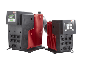
 Fig. 1: The Siflow FC070 Ex is an intrinsically safe Coriolis flow transmitter. It is approved for use in hazardous areas, holding the FM, CUL and ATEX approvals, and can be used with the whole range of Sitrans F C Coriolis flow sensors.
 -
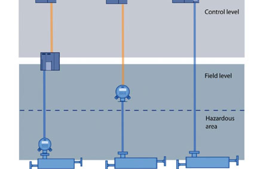 Fig. 2: Versus the traditional remote and compact mounted flowmetering solutions (2.1, 2.2), the ex-approved Siflow FC070 Coriolis flowmeter can be directly integrated in the control system (2.3).
In times of financial crises, the focus of interest for the chemical industry is on how to increase process efficiency. Easy access to process information and full process transparency are pivotal, but often rendered impossible by complex bus architecture. Especially when metering in hazardous areas. The solution is integral safety barriers enabling high speed communication directly integrated in the automation system.
Easy access to process data and full process transparency is obtained via a well constructed fieldbus system. However, in the chemical industry the working environment often consists of a mix of safe and hazardous areas. This places strain on the fieldbus system and often results in a very complex bus architecture. In particular, the formats of communication approved for use in hazardous areas are restricted in number: In order not to exceed the maximum permissible energy level, only bus communication solutions operating at lower process speed rates are allowed. As high speed communication is often specified in the safe areas of the plant, the general restrictions to communication in hazardous areas normally means that different solutions for hazardous and safe areas have to be found. Consequently data collection becomes less transparent, less easy.
Flow Metering in Hazardous Areas
There are two ways of installing the flowmeter, consisting of a transmitter and a sensor. While the flow sensor is installed in the hazardous area, the transmitter can be either an explosion proof compact mounted variant installed directly in the hazardous area or a remote mounted variant installed in the safe area.
The explosion proof compact mounted transmitter has the benefit of having a local display enabling programming and diagnosis directly in the hazardous area (fig. 2.1). However, this solution is normally very costly and furthermore, data collection and handling options are limited due to the safety requirements. The output from the explosion proof transmitter is low bandwidth and of reduced performance. In order to fully communicate with the PLC, a coupling module is normally necessary. This means additional costs - and a complex bus architecture.
A remote transmitter solution, on the other hand, is less expensive than the compact mounted variant, but also represents some challenges (fig. 2.2). The remote transmitter solution has full data collection and transportation capability, but requires an increased wiring complexity. As the transmitter receives the signal from the hazardous area, an additional safety barrier between the hazardous area and the safe area often has to be installed. Furthermore, sensor and transmitter interfaces are manufacturer specific, whereas bus interfaces are highly standardized. Again, a coupler module is normally required before communication with the PLC can take place.
Seamless Integration
As can be seen, there are a number of obstacles to overcome on the way towards easy access to process information and full process transparency. Thus, none of the above mentioned traditional solutions solve the communication problem in a satisfactory way. In both cases, costs are generated by additional hardware components in the guise of coupling modules. Furthermore, the complexity of the required fieldbus system means that considerable training expenses must be taken into account.
The alternative of sticking to the old analog input solutions based on a 4 - 20 mA control loop that only give access to one process value at a time and then supply with a HART fieldbus system is really not viable as it does not provide fast data and parameter access.
The obstacles, however, can be circumvented: The remote mounted Siflow FC070 Ex transmitter provides a non-compromising high speed communication solution, as it can be seamlessly integrated into Simatic based automation systems (fig. 2.3). In this way, a comprehensible fieldbus system can be attained and additional training expenses and hardware components such as coupling modules or cables avoided. Wiring complexity in the hazardous application is thus reduced to an absolute minimum, because the Ex barrier is an integral part of the Siflow FC070 Ex, enabling an intrinsically safe direct connection between sensor and transmitter. With a size of no more than 80 mm for the Ex-version, it perfectly matches the well renowned Simatic design features. Of even more importance, users of the Siflow FC070 Ex are experiencing the same interface consistency available in the full breadth and depth of Siemens instrumentation and control systems. The integration furthermore means that it becomes easier than ever to read out diagnostic information. Experience has shown that the reliability of diagnostics feedback is of outmost importance for ensuring the continued reliability of the meters and the easier access to diagnostic information is of paramount importance for reducing downtime and increasing safety.
Enhanced Accuracy
Process efficiency can thus be obtained by constructing a simple and transparent bus architecture even when the plant consists of a mix of hazardous and safe areas. However, process efficiency can also be increased by other means. An increased use of Coriolis flowmeters can contribute significantly in reaching that goal, as they are of paramount importance when it comes to process control and monitoring. Coriolis meters ensure a very high accuracy, and their performance is unaffected by changes in process variables, such as fluid density, pressure, viscosity, temperature and flow profile. Furthermore, the Coriolis flow meters are compatible with any fluid, including highly aggressive and non-conductive chemicals. It is additionally important that the Coriolis flowmeters are low-maintenance instruments with no moving parts subject to wear. After many years of service, they will continue to perform with the same high accuracy as on the very first day.
Contact
Siemens AG Industry Automation Division
Gleiwitzerstr. 555
90475 Nürnberg
Germany
+49 911 895-0
+49 911 895-154013